Legacy · Mechanical validation · §8.3 / Fig. 6c
Hollow cylinder (Fig. 6c)
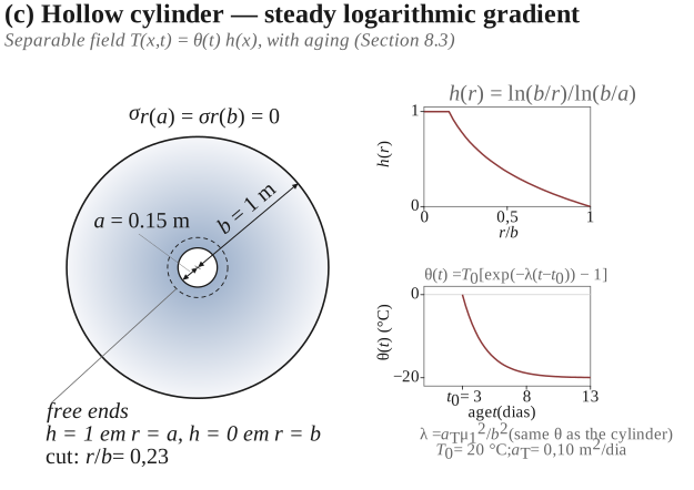
Separable thermal field — §8.3 / Figure 6(c). Uses the same (and ) as the solid cylinder.
Article: Part I · DOI rirc.v1n2a007
Mechanical material: Itumbiara — ; . Diffusivity: (do not confuse with ). Idea: ⇒ .
Control points (all Fig. 6 cases): ref_fig6_pontos_controle.csv.
Schematic
Data sheet
| Item | Value |
|---|---|
| Geometry | Long hollow cylinder: inner radius , outer |
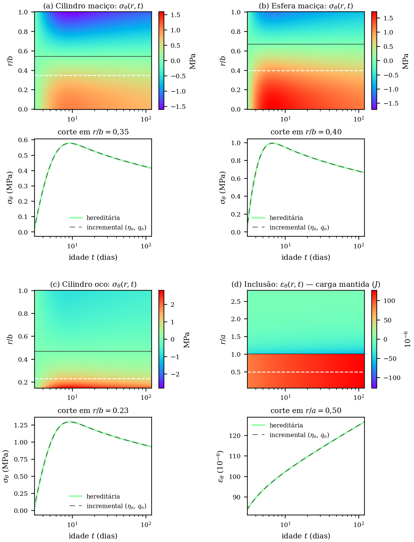
| Readout cut | (i.e. ) |
| Boundary | ; free ends |
| (steady state) | |
| same as the solid cylinder () | |
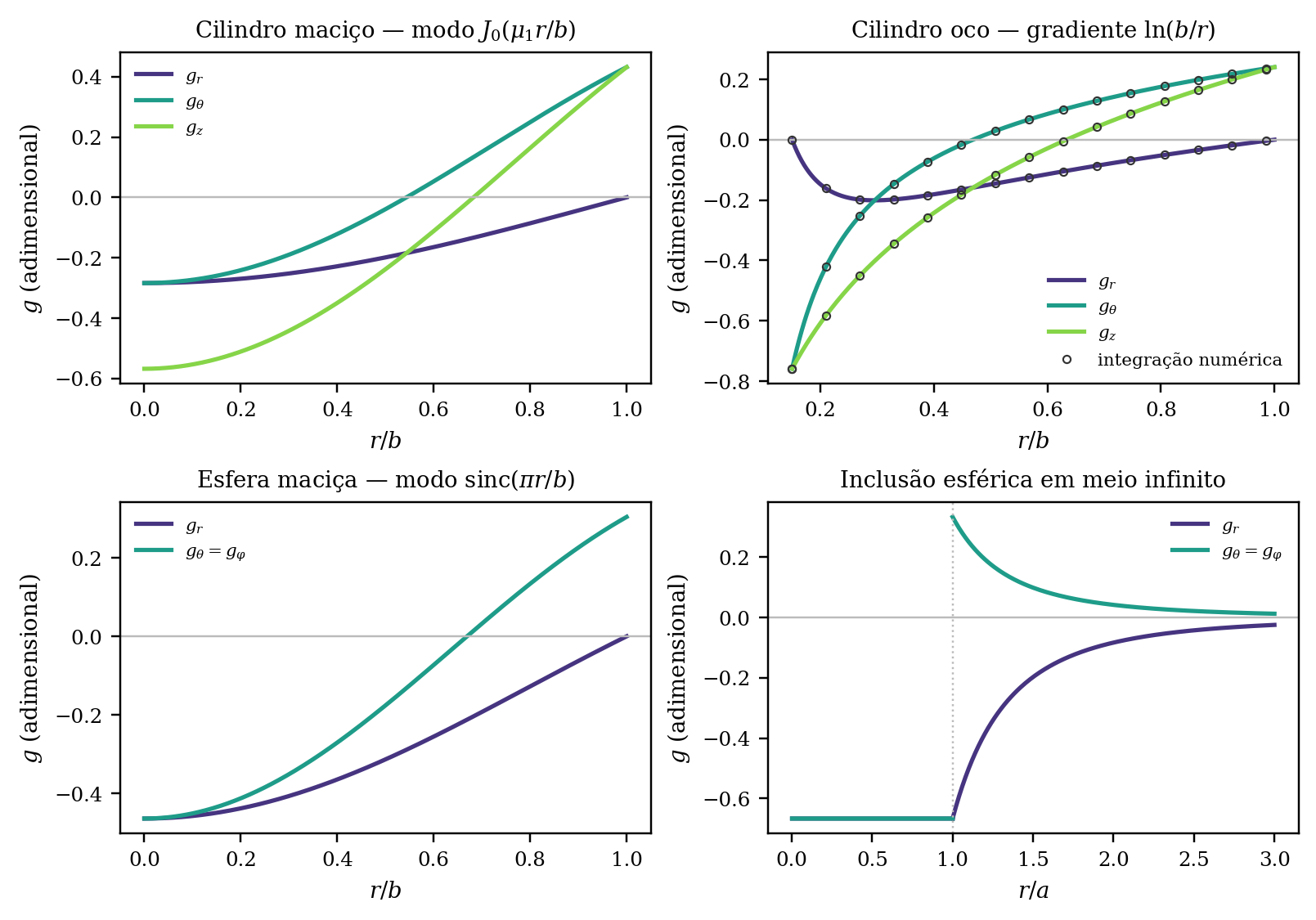
| Control point | in the CSV (numerical integration of the map); the closed form T&G (hollow_cylinder_log_closed_form) gives — difference ~0.07%, typically from radial discretisation |
Input files
- ref_cilindro_oco_theta.csv
- Material: Itumbiara
Output figures
 · Contours
Output files
Time mesh and tolerance
Same Fig. 6 mesh: age_grid(3, 123, 240). Expected tolerance ~0.2% on the temporal incremental response (see solid cylinder).